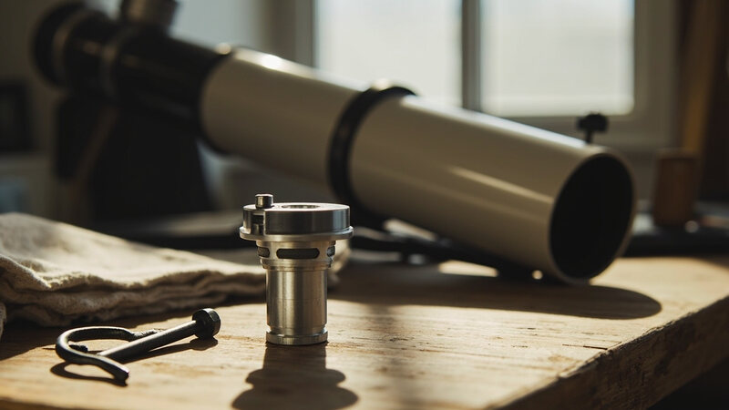
How to Collimate a Reflector With a Cheshire Eyepiece
Two mirrors decide whether a reflector shows sharp stars. Set them out of line and every planet at 200x grows a soft edge, and the fix is three screws on the secondary plus six on the primary. A 1.25 in Cheshire collimating eyepiece and one hex key cover the steps below in about ten minutes.
Our worked examples use a 203 mm (8 in) f/6 Dobsonian with a 1,200 mm focal length. Its useful range runs from 29x to 406x, and the second of those numbers is where a misaligned mirror starts to cost you detail.
- Tool
- 1.25 in Cheshire optical collimating eyepiece
- Secondary screws
- 3, spaced 120 degrees
- Primary screws
- 3 per side, 6 in all
- Reference scope
- 203 mm f/6, 1,200 mm
- Working light
- Daylight, tube level
- Judgement
- Big circle and dark centre on the crosshair
Math: tilt = pitch / radius; power = focal length / eyepiece focal length. Reference: 203 mm aperture, 1,200 mm focal length, 25, 10 and 6 mm eyepieces at 52 degrees. Listings read 2026-11-02.
What collimation fixes
Collimation lines up two optical axes: the axis of the primary mirror and the axis of the secondary have to meet at the focuser. When they do, the light from one mirror lands where the light from the other lands.
What you get back is the shape of a star. A tilted secondary tilts the beam, and the result is coma: a bright core with a tail, or a ring of light at the edge of the field.
The same error spreads the other axis, and that shows as astigmatism: a star is sharp along one direction and soft across the other.
At 48x the coma and the astigmatism do not show. At 25 mm the reference scope gives 1,200 / 25 = 48x and a true field of 52 / 48 = 1.08 degrees. A star looks like a point. Swap to the 10 mm at 120x with a 0.43 degree field and the tails show. At 200x the edge of a disc goes soft.
What collimation does not fix matters just as much. Aperture stays aperture. Seeing, sky brightness and focus belong to the night and to the eyepiece. A sagging cell and a focuser with play survive a perfect collimation.
Redo the job when the tube has been moved, bumped or opened. A machine that never moves does not need a schedule.
A 150 mm (6 in) tube needs the same routine; the 6-inch page covers what it shows.
The three circles in the Cheshire view
A Cheshire eyepiece shows the alignment as three circles. Name them before you touch a screw.
The biggest one is the whole primary mirror, reflected in the secondary; the spider vanes cross it. The faint ring inside is the primary's second image: light that leaves the primary, hits the secondary, comes back to the primary, and off again. The small dark circle at the centre is the secondary's shadow, the little secondary silhouetted against the primary's view.
The faint ring belongs to the primary as well, so it travels with the dark centre, not a step of its own. Two readings do the work: the secondary's screws bring the big circle onto the crosshair, and the primary's screws bring the dark centre onto it.
The judgement is one sentence: the big circle centred on the crosshair, the dark centre on it, and the faint ring between them. Anything off the crosshair means the job is not finished.
The tool itself is simple: a 45 degree plate with a fine crosshair, a peephole in the top, and a barrel that fits a 1.25 in focuser. No batteries, and the plate reflects daylight, so the job runs in daylight.
Point the tube at a bright, even surface. A white wall is easier than the sky, because a bare tube sees the wall twice: directly, and again in the plate.
Each circle is a different bounce, and that is why the big circle moves when you tip the secondary.
Step 1: centre the secondary mirror
Set the tube up first. Daylight, a white wall or an open bright area, and the tube lying level. Then check it: push the tube sideways and let go. If it rocks, the collimation will not hold, so fix the wobble before you turn a screw.
Take the 90 degree diagonal out and look down the focuser. The secondary should sit centred in there: if its shadow is off to one side, loosen the three screws on its holder and slide it until it does.
Then put the Cheshire straight into the focuser. The diagonal sends the light sideways and adds a surface to the path. The Cheshire wants the light to come straight back.
Now the secondary. Most Newtonians carry three collimation screws on its holder, 120 degrees apart. Their job in the eyepiece is the tilt.
What they move is the primary's image, the big circle. Loosen one and tighten the next a fraction of a turn at a time, and it swings across the field. Centre it on the crosshair and the secondary points at the focuser.
This is where a first attempt usually goes wrong. The primary's screws cannot swing the big circle, so if you chase it with the mirror cell, the two never agree.
A 2 in focuser needs an adapter, and the adapter sits on the focuser side. The Cheshire stays 1.25 in, because that is the barrel that carries the plate and the crosshair. The eyepiece page keeps the two thread sizes in one place.
Step 2: collimate the primary mirror
With the primary's image centred, the mirror cell takes over. Most Newtonians carry three collimation screws per side of the primary cell, six in all. Count them on your own tube, because the number differs between models.
The target is the dark centre. The secondary's shadow has to sit on the crosshair, in the middle of the big circle. When the shadow and the big circle share the crosshair, the beam is lined up.
The work is slow on purpose. Turn one screw, then look. A quarter turn is too much; an eighth of a turn is a good step. You should be able to watch the shadow move towards the crosshair as you go.
Check the screws before you start. If one is bottomed out, it can only push. If one has play in its hole, it pushes the cell one way and the cell springs back. Either way the other screws have to undo the same movement, and the last adjustment never settles.
The faint ring moves with the shadow. If the shadow is centred but the faint ring sits off to one side, the primary screws still have work to do.
Step 3: how far one turn of a screw moves the beam
You do not have to count turns. The geometry gives the angle. The tilt of the beam is roughly the thread pitch divided by the distance from the screw to the optical axis: tilt = p / r, in radians.
Take a 1/4-20 screw, the thread many Dobs use. Its pitch is 25.4 / 20 = 1.27 mm per turn. Put the screw 25 mm from the axis and 1.27 / 25 = 0.051 rad, which is about 2.9 degrees for one full turn. An eighth of a turn is about 0.36 degrees.
That is why the last part of the job takes patience. 0.36 degrees is a small move on screen, and your eye has to find it.
Two measurements give you the numbers. Take one screw out, measure five turns of the thread, and divide by five for the pitch. Then measure from the inside wall of the tube to the centre of the screw for r. The thread depends on the model, so check the maker's parts list instead of assuming 1/4-20.
One habit saves trouble. Back each screw off half a turn before you start, then bring it back gently. A screw's tightness is part of what holds the mirror in place, so changing it changes the axis you are trying to line up.
Symptom lookup: what you see and what it means
Seven symptoms cover most of what turns up in the eyepiece. Each row gives the turn to make and the reading that follows it.
| What you see | What it means | Where to turn | The test |
|---|---|---|---|
| Secondary shadow off centre in the focuser | The secondary is not centred | Step 1, centring | Shadow centred in the focuser |
| Big circle off the crosshair | The secondary is tilted | Step 1, tilt | Big circle centred |
| Big circle centred, shadow off | The primary is off | Step 2, primary screws | Shadow on the crosshair |
| Shadow centred, big circle off | The secondary moved afterwards | Step 1, tilt again | Big circle centred |
| One screw moves the others too | A screw is tight or loose | Step 2, free the screws first | Each screw moves alone |
| Circles centred, stars still fringed | Residual error or a moving tube | Check for play, then repeat | Round stars at 120x |
| Only one circle in the view | Secondary off axis, or light leaks | Step 1, then the tube | Three circles in the view |
The tools each step needs
Here is the same job as a table. Each row is one action: the tool it uses, where the tool goes, and the reading that ends the step.
Our assumptions first, so every number in the table can be checked: a 203 mm (8 in) f/6 Dobsonian with a 1,200 mm focal length, a 52 degree apparent field on the eyepiece rows, and daylight work with the tube level and the tube left in place.
| Step | What to do | Tool | Where it goes | Which screws | The test |
|---|---|---|---|---|---|
| 1 Set up | Level the tube | Hex key | The tube | None | It does not rock |
| 2 Centre the secondary | Slide it into the focuser | None | Focuser | Secondary, 3 at a time | Shadow centred |
| 3 Fit the eyepiece | Take the diagonal out | Cheshire, 1.25 in | Straight into the focuser | None | The crosshair shows |
| 4 Tilt the secondary | Big circle to the crosshair | Cheshire | Focuser | Secondary, 2 at a time | Big circle centred |
| 5 Align the primary | Dark centre to the crosshair | Cheshire and hex key | Focuser | Primary, 3 per side | Shadow on the crosshair |
| 6 Recheck and lock | Look again, tighten | Cheshire | Focuser | All of them | Circles still concentric |
| 7 Verify on the sky | Check stars at 48x and 120x | 25 mm and 10 mm | Focuser | None | Round stars at 120x |
The eyepiece does the measuring and you do the turning. A 1.25 in barrel drops into a standard focuser, and the 45 degree plate puts the crosshair and the reflection in the same view, so you never have to swap a piece to check the circles.
Secondary mirror knobs: match the thread, not the brand
The secondary's three screws take a hex key, and a hex key next to the eyepiece is awkward. A knob set replaces the screw heads with hand-turned knobs, so you can centre and tilt the secondary with your fingertips.
The rule is to buy by model, not by size. Two numbers have to match: the thread of the secondary's screws, and the diameter of the seat they screw into. A knob with the right thread and the wrong head will not fit. A knob with the right head and the wrong thread will not bite.
Measure before you order. Put a calliper across the screw heads and write the diameter down. Take the thread from the maker's parts list for your scope. Then read the listing for the set and check that both numbers appear.
The knob sets in these listings are cut for one named model each. The set below is cut for the Astro-Tech AT12RC secondary, and the listing names the model rather than a thread size or a knob diameter.
Dry fit the set before the first collimation. The knobs should turn by hand, and the secondary should still move a little when you nudge them. If a knob will not turn, back it off one notch and try again, because a knob that binds pushes the mirror off centre.
How to tell it is done
Collimating changes the axis, not the focus. Refocus before you judge the result, or you will blame the collimation for a focus problem.
Three eyepieces cover the check, and the numbers come from the same 1,200 mm reference scope.
At 25 mm: 1,200 / 25 = 48x, a true field of 52 / 48 = 1.08 degrees, and an exit pupil of 203 / 48 = 4.2 mm. At that power the test is steadiness. The field edge should sit still when you nudge the tube, and a star should stay a point.
At 10 mm: 120x, 52 / 120 = 0.43 degrees, and 203 / 120 = 1.7 mm. This is the real test. A star should be round, with no fringe on either side, and it should not change shape as you move it across the field.
At 6 mm: 200x, 0.26 degrees, and 203 / 200 = 1.0 mm. Use this on a steady night only. The aperture is finished at 406x, which is 2 x 203, and above that the extra power only makes the image bigger.
One limit is worth knowing. A 1.25 in eyepiece stops the field at its 27 mm stop: 27 / 1,200 x 57.2958 = 1.29 degrees. The 25 mm shows 1.08 degrees, so nothing clips.
Which body fits your tube
Two bodies come for the same 1.25 in barrel. The short one is 6 in long and 1.3 in wide, and it clears a fast Newtonian tube where the focuser sits close to the primary. The long one is 6 in long and 1.4 in wide, and its reach suits a focuser set further back.
Neither reads the circles differently: both carry a 45 degree plate and a crosshair, so the view looks the same in either body. A printed plate reads them as well: 45 degrees, a fine crosshair, and a hole through the top for the light.
Common Questions
What does collimating a telescope actually do?
It lines up the optical axis of the primary mirror with that of the secondary, so the light from both lands in the same place. At 48x the difference is invisible, at 120x it is obvious, at 200x a disc and a smear.
How often does a telescope need collimating?
After the tube moves, gets bumped, or comes apart. A machine that stays in one place does not need a schedule. A long road trip is enough to shift a set of mirrors out of line.
Do new telescopes need collimating before first light?
Look through it first. A new Dobsonian usually arrives with its mirrors set, and a check costs ten minutes. If the circles do not line up, the cell shifted.
Is collimating hard?
The secondary is the hard part, because centring it and tilting it pull against each other. The primary is easier: six screws and one shadow to aim.
Which collimating tool does a Newtonian need?
One 1.25 in Cheshire collimating eyepiece covers every step above. The barrel has to match your focuser, and the plate keeps the crosshair and the reflection in one view.
Read next
- Telescope typesWhich telescopes need collimating
- What you can seeWhat an 8-inch telescope shows
- ToolsEyepiece field of view calculator
- EyepiecesHow to choose telescope eyepieces
Sources
- Formulas: magnification = focal length / eyepiece focal length; true field = apparent field / magnification; exit pupil = aperture / magnification; maximum useful power = 2 x aperture in mm; minimum useful power = aperture / 7; field stop = stop / focal length x 57.2958. Method: How we research.
- Reference scope 203 mm and 1,200 mm, and the 25, 10 and 6 mm rows at 52 degrees, from the eyepiece calculator.
- 27 mm field stop in a 1.25 in barrel, as used on the eyepiece page.
- Listings read 2026-11-02: Astromania short version (1.25 in barrel, 45 degree plate, aluminium crosshair, 6 x 1.3 x 1.3 in); long version (6 x 1.4 x 1.4 in, 1 item); Bobs Knobs AT12RC (model named, no dimensions published). The short body says to cap the tube, remove the diagonal and fit the eyepiece into the focuser.
- Collimation method: Celestron's Newtonian collimation guide: the primary's image is the big circle, the secondary's shadow the dark centre; read 2026-11-02.
- Screw tilt: our own count, not a printed rule. Tilt = pitch / radius: 1/4-20 gives 25.4 / 20 = 1.27 mm per turn, and 1.27 / 25 = 0.051 rad, 2.9 degrees.
How we check numbers: How we research.